Product Description
Flexible Flex Fluid Chain Jaw Flange Gear Rigid Spacer Pin HRC Mh Nm Universal Fenaflex Oldham Spline Clamp Tyre Grid Hydraulic Servo Motor Shaft Coupling
Features
Material: cast iron GG25, GG20 steel: C45
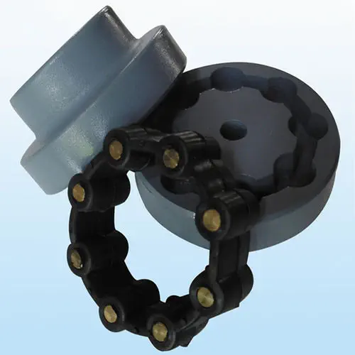
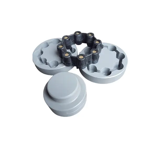
Parts: 2 couplings and 1 tire body.
Size from F40-F250. and Type: “B”, “F”, “H”.
Working temp: -20~80ºC
Transmission torque:10-20000N.M
Axial misalignment: D*2%
Radial deviation: D*1%
Angular misalignment:3°-6°
Application: tire couplings are usually used in wet, dusty, under attract, vibration, rotating, and complex working conditions. like: diesel pump
Installation: easy on, easy off.
Maintenance: no need for lubricating and durability.
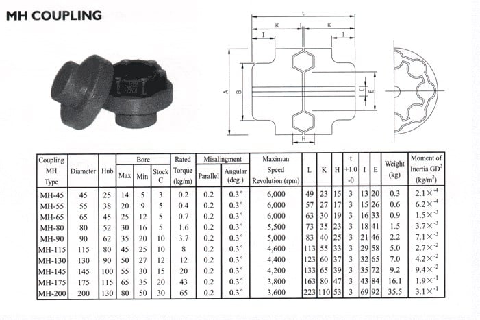
Product Description
| Size | Type | Bush No. | MaxBore | Type F&H | Type H | Serve over Key |
A | C | D | F | M | |||
| mm | Inch | L | E | L | E | |||||||||
| F40 | B | – | 32 | – | – | – | 33 | 22 | M5 | 104 | 82 | – | – | 11 |
| F40 | F | 1008 | 25 | 1″ | 33 | 22 | – | – | – | 104 | 82 | – | – | 11 |
| F40 | H | 1008 | 25 | 1″ | 33 | 22 | – | – | – | 104 | 82 | – | – | 11 |
| F50 | B | – | 38 | – | – | – | 43 | 32 | M5 | 133 | 100 | 79 | – | 12.5 |
| F50 | F | 1210 | 32 | 1 1/4″ | 38 | 25 | – | – | – | 133 | 100 | 79 | – | 12.5 |
| F50 | H | 1210 | 32 | 1 1/4″ | 38 | 25 | – | – | – | 133 | 100 | 79 | – | 12.5 |
| F80 | B | – | 45 | – | – | – | 55 | 33 | M6 | 165 | 125 | 70 | – | 16.5 |
| F80 | F | 1610 | 42 | 1 5/8″ | 42 | 25 | – | – | – | 165 | 125 | 103 | – | 16.5 |
| F60 | H | 1610 | 42 | 1 5/8″ | 42 | 25 | – | – | – | 165 | 125 | 103 | – | 16.6 |
| F70 | B | – | 50 | – | – | – | 47 | 35 | M8 | 187 | 142 | 80 | 60 | 11.5 |
| F70 | F | 2012 | 50 | 2″ | 44 | 32 | – | – | – | 187 | 142 | 80 | 50 | 11.5 |
| F70 | H | 1810 | 42 | 1 5/8″ | 42 | 25 | – | – | – | 187 | 142 | 80 | 50 | 11.5 |
| F80 | B | – | 60 | – | – | – | 55 | 42 | M8 | 211 | 165 | 98 | 54 | 12.5 |
| F80 | F | 2517 | 80 | 2 1/2″ | 58 | 45 | – | – | – | 211 | 165 | 98 | 54 | 12.5 |
| F80 | H | 2012 | 50 | 2″ | 45 | 32 | – | – | – | 211 | 165 | 98 | 54 | 12.5 |
| F90 | H | – | 70 | – | – | – | 63.5 | 49 | M10 | 235 | 188 | 108 | 62 | 13.5 |
| F90 | F | 2517 | 60 | 2 1/2″ | 58.5 | 45 | – | – | – | 235 | 188 | 108 | 62 | 13.5 |
| F90 | H | 2517 | 60 | 2 1/2″ | 58.5 | 45 | – | – | – | 235 | 188 | 108 | 62 | 13.5 |
| F100 | H | – | 80 | – | – | – | 63.5 | 49 | M10 | 235 | 188 | 120 | 62 | 13.5 |
| F100 | F | 3571 | 75 | 3″ | 64.5 | 51 | – | – | – | 235 | 188 | 125 | 62 | 13.5 |
| F100 | H | 2517 | 60 | 2 1/2″ | 58.5 | 45 | – | – | – | 235 | 188 | 113 | 62 | 13.5 |
| F110 | B | – | 90 | – | – | – | 75.5 | 63 | M12 | 279 | 233 | 128 | 62 | 12.5 |
| F110 | F | 3571 | 75 | 3″ | 63.5 | 51 | – | – | – | 279 | 233 | 134 | 62 | 12.5 |
| F110 | H | 3571 | 75 | 3″ | 63.5 | 51 | – | – | – | 279 | 233 | 134 | 62 | 12.5 |
| F120 | B | – | 100 | – | – | – | 84.5 | 70 | M12 | 314 | 264 | 140 | 67 | 14.5 |
| F120 | F | 3525 | 100 | 4″ | 79.5 | 65 | – | – | – | 314 | 264 | 144 | 67 | 14.5 |
| F120 | H | 3571 | 75 | 4″ | 85.5 | 51 | – | – | – | 314 | 264 | 144 | 67 | 14.5 |
| F140 | B | – | 130 | – | – | – | 110.5 | 4 | M16 | 359 | 311 | 178 | 73 | 16 |
| F140 | F | 3525 | 100 | 4″ | 81.5 | 65 | – | – | – | 359 | 311 | 178 | 73 | 16 |
| F140 | H | 3525 | 100 | 4″ | 81.5 | 65 | – | – | – | 359 | 311 | 178 | 73 | 18 |
| F160 | B | – | 140 | – | – | – | 117 | 102 | M20 | 402 | 345 | 187 | 78 | 16 |
| F160 | F | 4030 | 115 | 4 1/2″ | 92 | 77 | – | – | – | 402 | 345 | 197 | 78 | 16 |
| F160 | H | 4030 | 115 | 4 1/2″ | 92 | 77 | – | – | – | 402 | 345 | 197 | 78 | 16 |
| F180 | B | – | 150 | – | – | – | 137 | 114 | M16 | 470 | 394 | 205 | 94 | 23 |
| F180 | F | 4536 | 125 | 5″ | 112 | 89 | – | – | – | 470 | 394 | 205 | 94 | 23 |
| F180 | H | 4535 | 125 | 5″ | 112 | 89 | – | – | – | 470 | 394 | 205 | 94 | 23 |
| F200 | B | – | 150 | – | – | – | 138 | 114 | M20 | 508 | 429 | 205 | 103 | 24 |
| F200 | F | 4535 | 125 | 5″ | 113 | 89 | – | – | – | 508 | 429 | 205 | 103 | 24 |
| F200 | H | 4535 | 125 | 5″ | 113 | 89 | – | – | 508 | 429 | 205 | 103 | 24 | |
| F220 | B | – | 160 | – | – | – | 154.5 | 127 | M20 | 562 | 474 | 223 | 118 | 27.5 |
| F220 | F | 5571 | 125 | 5″ | 129.5 | 102 | – | – | – | 562 | 474 | 223 | 118 | 27.5 |
| F220 | H | 5571 | 125 | 5″ | 129.5 | 102 | – | – | – | 562 | 474 | 223 | 118 | 27.5 |
| F250 | H | – | 190 | – | – | 161.5 | 132 | M20 | 628 | 522 | 254 | 125 | 29.5 | |
Related Products
Company Profile
FAQ
Q: How to ship to us?
A: It is available by air, sea, or train.
Q: How to pay the money?
A: T/T and L/C are preferred, with different currencies, including USD, EUR, RMB, etc.
Q: How can I know if the product is suitable for me?
A: >1ST confirm drawing and specification >2nd test sample >3rd start mass production.
Q: Can I come to your company to visit?
A: Yes, you are welcome to visit us at any time.
|
Shipping Cost:
Estimated freight per unit. |
To be negotiated |
|---|
| Standard Or Nonstandard: | Standard |
|---|---|
| Shaft Hole: | 25-190 |
| Torque: | 10-30N.M |
| Samples: |
US$ 5/Piece
1 Piece(Min.Order) | Order Sample |
|---|
| Customization: |
Available
| Customized Request |
|---|
Can flexible couplings be used in both horizontal and vertical shaft arrangements?
Yes, flexible couplings can be used in both horizontal and vertical shaft arrangements. The design of flexible couplings allows them to accommodate misalignment and compensate for angular, parallel, and axial displacements between the shafts, making them suitable for various shaft orientations.
Horizontal Shaft Arrangements:
In horizontal shaft arrangements, where the shafts are parallel to the ground or horizontal plane, flexible couplings are commonly used to connect two rotating shafts. These couplings help transmit torque from one shaft to another while accommodating any misalignment that may occur during operation. Horizontal shaft arrangements are common in applications such as pumps, compressors, conveyors, and industrial machinery.
Vertical Shaft Arrangements:
In vertical shaft arrangements, where the shafts are perpendicular to the ground or vertical plane, flexible couplings are also applicable. Vertical shafts often require couplings that can handle the additional weight and forces resulting from gravity. Flexible couplings designed for vertical applications can support the weight of the rotating equipment while allowing for some axial movement to accommodate thermal expansion or other displacements. Vertical shaft arrangements are commonly found in applications such as pumps, gearboxes, turbines, and some marine propulsion systems.
Considerations for Vertical Shaft Arrangements:
When using flexible couplings in vertical shaft arrangements, there are a few additional considerations to keep in mind:
- Thrust Load: Vertical shafts can generate thrust loads, especially in upward or downward direction. The flexible coupling should be selected based on its capacity to handle both radial and axial loads to accommodate these forces.
- Lubrication: Some vertical couplings may require additional lubrication to ensure smooth operation and reduce wear, particularly if they are exposed to high axial loads or extended vertical shafts.
- Support and Bearing: Proper support and bearing arrangements for the vertical shaft are essential to prevent excessive shaft deflection and ensure the flexible coupling functions correctly.
Overall, flexible couplings are versatile and adaptable to various shaft orientations, providing efficient power transmission and misalignment compensation. Whether in horizontal or vertical arrangements, using the appropriate flexible coupling design and considering the specific application requirements will help ensure reliable and efficient operation.
How does a flexible coupling handle angular, parallel, and axial misalignment?
A flexible coupling is designed to accommodate various types of misalignment between two rotating shafts: angular misalignment, parallel misalignment, and axial misalignment. The flexibility of the coupling allows it to maintain a connection between the shafts while compensating for these misalignment types. Here’s how a flexible coupling handles each type of misalignment:
- Angular Misalignment: Angular misalignment occurs when the axes of the two shafts are not collinear and form an angle with each other. Flexible couplings can handle angular misalignment by incorporating an element that can flex and bend. One common design is the “spider” or “jaw” element, which consists of elastomeric materials. As the shafts are misaligned, the elastomeric element can deform slightly, allowing the coupling to accommodate the angular offset between the shafts while still transmitting torque.
- Parallel Misalignment: Parallel misalignment, also known as offset misalignment, occurs when the axes of the two shafts are parallel but not perfectly aligned with each other. Flexible couplings can handle parallel misalignment through the same elastomeric element. The flexible nature of the element enables it to shift and adjust to the offset between the shafts, ensuring continuous power transmission while minimizing additional stresses on the machinery.
- Axial Misalignment: Axial misalignment, also called end-play misalignment, occurs when the two shafts move closer together or farther apart along their common axis. Flexible couplings can handle axial misalignment through specific designs that allow limited axial movement. For instance, some couplings use slotted holes or a floating member that permits axial displacement while maintaining the connection between the shafts.
By providing the capability to handle angular, parallel, and axial misalignment, flexible couplings offer several advantages for power transmission systems:
- They help to prevent premature wear and damage to the connected equipment, reducing maintenance and replacement costs.
- They minimize vibration and shock loads, enhancing the overall smoothness and reliability of the machinery.
- They reduce the risk of equipment failure due to misalignment-induced stresses, improving the system’s operational life.
- They allow for easier installation and alignment adjustments, saving time and effort during setup and maintenance.
Overall, flexible couplings play a crucial role in handling misalignment and ensuring efficient power transmission in various industrial applications.
What materials are commonly used in manufacturing flexible couplings?
Flexible couplings are manufactured using a variety of materials, each offering different properties and characteristics suited for specific applications. The choice of material depends on factors such as the application’s requirements, environmental conditions, torque capacity, and desired flexibility. Here are some of the commonly used materials in manufacturing flexible couplings:
- Steel: Steel is a widely used material in flexible couplings due to its strength, durability, and excellent torque transmission capabilities. Steel couplings are suitable for heavy-duty industrial applications with high torque requirements and harsh operating conditions.
- Stainless Steel: Stainless steel is often used to manufacture flexible couplings in environments with high corrosion potential. Stainless steel couplings offer excellent resistance to rust and other corrosive elements, making them ideal for marine, food processing, and chemical industry applications.
- Aluminum: Aluminum couplings are lightweight, have low inertia, and provide excellent balance. They are commonly used in applications where reducing weight is critical, such as aerospace and robotics.
- Brass: Brass couplings are known for their electrical conductivity and are used in applications where electrical grounding or electrical isolation is required, such as in certain industrial machinery or electronics equipment.
- Cast Iron: Cast iron couplings offer good strength and durability and are often used in industrial applications where resistance to shock loads and vibrations is necessary.
- Plastic/Polymer: Some flexible couplings use high-performance polymers or plastics, such as polyurethane or nylon. These materials provide good flexibility, low friction, and resistance to chemicals. Plastic couplings are suitable for applications where corrosion resistance and lightweight are essential.
- Elastomers: Elastomers are used as the flexible elements in many flexible couplings. Materials like natural rubber, neoprene, or urethane are commonly used as elastomer spider elements, providing flexibility and vibration damping properties.
The selection of the coupling material depends on the specific needs of the application. For instance, high-performance and heavy-duty applications may require steel or stainless steel couplings for their robustness, while applications where weight reduction is crucial may benefit from aluminum or polymer couplings. Additionally, the choice of material is influenced by factors such as temperature range, chemical exposure, and electrical requirements in the application’s operating environment.
Manufacturers typically provide material specifications for their couplings, helping users make informed decisions based on the specific demands of their applications.


editor by CX 2023-08-08