Product Description
Product Description
COUPLINGS
| HRC | FCL | Chain coupling | GE | L | NM | MH | Torque limiter |
| HRC 70B | FCL90 | KC4012 | GE14 | L050 | NM50 | MH45 | TL250-2 |
| HRC 70F | FCL100 | KC4014 | GE19 | L070 | NM67 | MH55 | TL250-1 |
| HRC 70H | FCL112 | KC4016 | GE24 | L075 | NM82 | MH65 | TL350-2 |
| HRC 90B | FCL125 | KC5014 | GE28 | L090 | NM97 | MH80 | TL350-1 |
| HRC 90F | FCL140 | KC5016 | GE38 | L095 | NM112 | MH90 | TL500-2 |
| HRC 90H | FCL160 | KC6018 | GE42 | L099 | NM128 | MH115 | TL500-1 |
| HRC 110B | FCL180 | KC6571 | GE48 | L100 | NM148 | MH130 | TL700-2 |
| HRC 110F | FCL200 | KC6571 | GE55 | L110 | NM168 | MH145 | TL700-1 |
| HRC 110H | FCL224 | KC8018 | GE65 | L150 | NM194 | MH175 | |
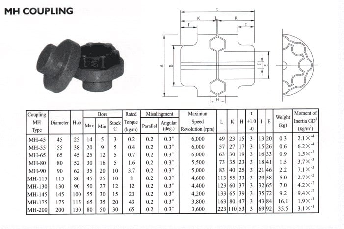
| HRC 130B | FCL250 | KC8571 | GE75 | L190 | NM214 | MH200 | |
| HRC 130F | FCL280 | KC8571 | GE90 | L225 | |||
| HRC 130H | FCL315 | KC1571 | |||||
| HRC 150B | FCL355 | KC12018 | |||||
| HRC 150F | FCL400 | KC12571 | |||||
| HRC 150H | FCL450 | ||||||
| HRC 180B | FCL560 | ||||||
| HRC 180F | FCL630 | ||||||
| HRC 180H | |||||||
| HRC 230B | |||||||
| HRC 230F | |||||||
| HRC 230H | |||||||
| HRC 280B | |||||||
| HRC 280F | |||||||
| HRC 280H |
Catalogue
Workshop
Lots of couplings in stock
FAQ
Q1: Are you trading company or manufacturer ?
A: We are factory.
Q2: How long is your delivery time and shipment?
1.Sample Lead-times: 10-20 days.
2.Production Lead-times: 30-45 days after order confirmed.
Q3: What is your advantages?
1. The most competitive price and good quality.
2. Perfect technical engineers give you the best support.
3. OEM is available.
| Standard Or Nonstandard: | Standard |
|---|---|
| Structure: | Flexible |
| Material: | Cast Iron |
| Type: | Elastic Coupling |
| Color: | Gray |
| Material of Element: | Rubber |
| Customization: |
Available
| Customized Request |
|---|
What are the maintenance requirements for flexible couplings?
Maintenance of flexible couplings is essential to ensure their reliable and efficient performance over their service life. Proper maintenance helps prevent premature wear, reduces the risk of unexpected failures, and extends the lifespan of the couplings. Here are some key maintenance requirements for flexible couplings:
- Regular Inspection: Perform regular visual inspections of the flexible couplings to check for signs of wear, damage, or misalignment. Look for cracks, tears, or any other visible issues in the coupling components.
- Lubrication: Some flexible couplings, especially those with moving parts or sliding surfaces, may require periodic lubrication. Follow the manufacturer’s recommendations regarding the type and frequency of lubrication to ensure smooth operation.
- Alignment Checks: Misalignment is a common cause of coupling failure. Regularly check the alignment of the connected shafts and adjust as necessary. Proper alignment reduces stress on the coupling and improves power transmission efficiency.
- Torque Monitoring: Monitoring the torque transmitted through the coupling can help detect any abnormal or excessive loads. If the coupling is subjected to loads beyond its rated capacity, it may lead to premature failure.
- Environmental Protection: If the couplings are exposed to harsh environmental conditions, take measures to protect them from dust, dirt, moisture, and corrosive substances. Consider using protective covers or seals to shield the couplings from potential contaminants.
- Temperature Considerations: Ensure that the operating temperature of the flexible coupling is within its designed range. Excessive heat can accelerate wear, while extremely low temperatures may affect the flexibility of certain coupling materials.
- Replace Worn or Damaged Parts: If any components of the flexible coupling show signs of wear or damage, replace them promptly with genuine replacement parts from the manufacturer.
- Manufacturer’s Guidelines: Follow the maintenance guidelines provided by the coupling manufacturer. They often include specific maintenance intervals and procedures tailored to the coupling’s design and materials.
- Training and Expertise: Ensure that maintenance personnel have the necessary training and expertise to inspect and maintain the flexible couplings properly. Improper maintenance practices can lead to further issues and compromise the coupling’s performance.
By adhering to these maintenance requirements, you can maximize the service life of the flexible couplings and minimize the risk of unexpected downtime or costly repairs. Regular maintenance helps maintain the efficiency and reliability of the coupling in various industrial, automotive, and machinery applications.
How does a flexible coupling handle angular, parallel, and axial misalignment?
A flexible coupling is designed to accommodate various types of misalignment between two rotating shafts: angular misalignment, parallel misalignment, and axial misalignment. The flexibility of the coupling allows it to maintain a connection between the shafts while compensating for these misalignment types. Here’s how a flexible coupling handles each type of misalignment:
- Angular Misalignment: Angular misalignment occurs when the axes of the two shafts are not collinear and form an angle with each other. Flexible couplings can handle angular misalignment by incorporating an element that can flex and bend. One common design is the “spider” or “jaw” element, which consists of elastomeric materials. As the shafts are misaligned, the elastomeric element can deform slightly, allowing the coupling to accommodate the angular offset between the shafts while still transmitting torque.
- Parallel Misalignment: Parallel misalignment, also known as offset misalignment, occurs when the axes of the two shafts are parallel but not perfectly aligned with each other. Flexible couplings can handle parallel misalignment through the same elastomeric element. The flexible nature of the element enables it to shift and adjust to the offset between the shafts, ensuring continuous power transmission while minimizing additional stresses on the machinery.
- Axial Misalignment: Axial misalignment, also called end-play misalignment, occurs when the two shafts move closer together or farther apart along their common axis. Flexible couplings can handle axial misalignment through specific designs that allow limited axial movement. For instance, some couplings use slotted holes or a floating member that permits axial displacement while maintaining the connection between the shafts.
By providing the capability to handle angular, parallel, and axial misalignment, flexible couplings offer several advantages for power transmission systems:
- They help to prevent premature wear and damage to the connected equipment, reducing maintenance and replacement costs.
- They minimize vibration and shock loads, enhancing the overall smoothness and reliability of the machinery.
- They reduce the risk of equipment failure due to misalignment-induced stresses, improving the system’s operational life.
- They allow for easier installation and alignment adjustments, saving time and effort during setup and maintenance.
Overall, flexible couplings play a crucial role in handling misalignment and ensuring efficient power transmission in various industrial applications.
Can you explain the different types of flexible coupling designs available?
There are several types of flexible coupling designs available, each with its unique construction and characteristics. These designs are tailored to meet specific application requirements and address different types of misalignment and torque transmission needs. Here are some of the most common types of flexible couplings:
- Jaw Couplings: Jaw couplings consist of two hubs with curved jaws and an elastomer spider placed between them. The spider acts as a flexible element and can compensate for angular and parallel misalignment. Jaw couplings are widely used in various industrial applications due to their simple design and effectiveness in handling misalignment and vibration damping.
- Disc Couplings: Disc couplings use thin metallic discs with a series of alternating slits and flanges to connect the shafts. The disc coupling design allows for excellent misalignment compensation, including angular, parallel, and axial misalignment. Disc couplings are known for their high torsional stiffness and precise torque transmission capabilities.
- Gear Couplings: Gear couplings consist of toothed hubs connected by an external sleeve with gear teeth. They are well-suited for applications with high torque and moderate misalignment. Gear couplings offer good misalignment compensation and high torque capacity, making them popular in heavy-duty industrial applications.
- Beam Couplings: Beam couplings use a single piece of flexible material, often a metal beam, to connect the shafts. The material’s flexibility allows for angular and axial misalignment compensation. Beam couplings are compact, lightweight, and provide low inertia, making them suitable for applications with high-speed requirements.
- Bellows Couplings: Bellows couplings consist of a bellows-like flexible structure that connects the two hubs. They can compensate for angular, parallel, and axial misalignment. Bellows couplings are known for their high torsional stiffness and ability to maintain constant velocity transmission.
- Oldham Couplings: Oldham couplings use three discs, with the middle one having a perpendicular slot. This design allows for angular misalignment compensation while transmitting torque between the hubs. Oldham couplings are often used when electrical isolation between shafts is required.
Each flexible coupling design has its strengths and limitations, and the choice depends on factors such as the application’s torque requirements, misalignment conditions, operating environment, and speed. Proper selection of the coupling type ensures optimal performance, efficiency, and reliability in various mechanical systems and rotating machinery.


editor by CX 2023-09-07